Precise control, restored
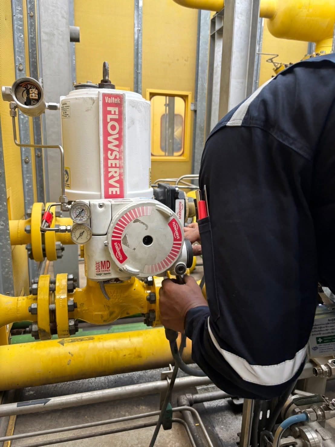
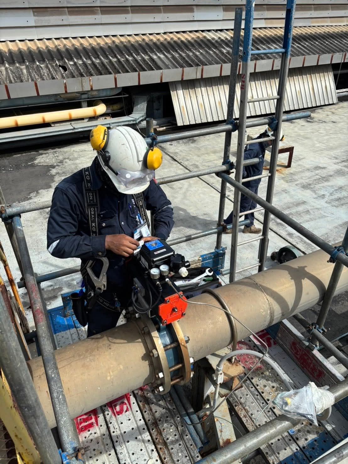
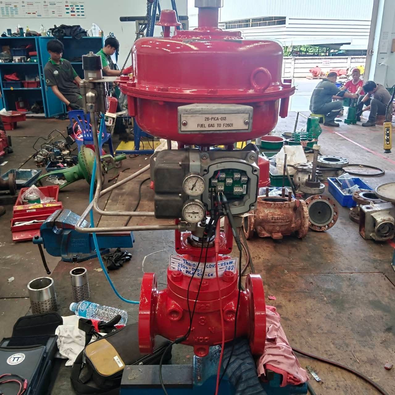
A control valve is only as good as the loop around it. We record and mark every component, then service the body, trim, actuator and positioner together — so the valve returns to accurate, repeatable process control, not just a tight shut-off.
* All brands and series (Masoneilan, Fisher and others), with actuator and positioner serviced to the original specification.
Certified control-valve capability
Tested to ANSI & API
Body hydrostatically tested to ANSI B16.34 / API 598, with seat-leakage tested and classified to ANSI/FCI 70-2 (Class I–VI).
Seat & plug precision lapping
Seat and plug lapped through a graded compound sequence to a fine, flat, single-color finish — machined first when damage runs deep.
Calibrated & documented
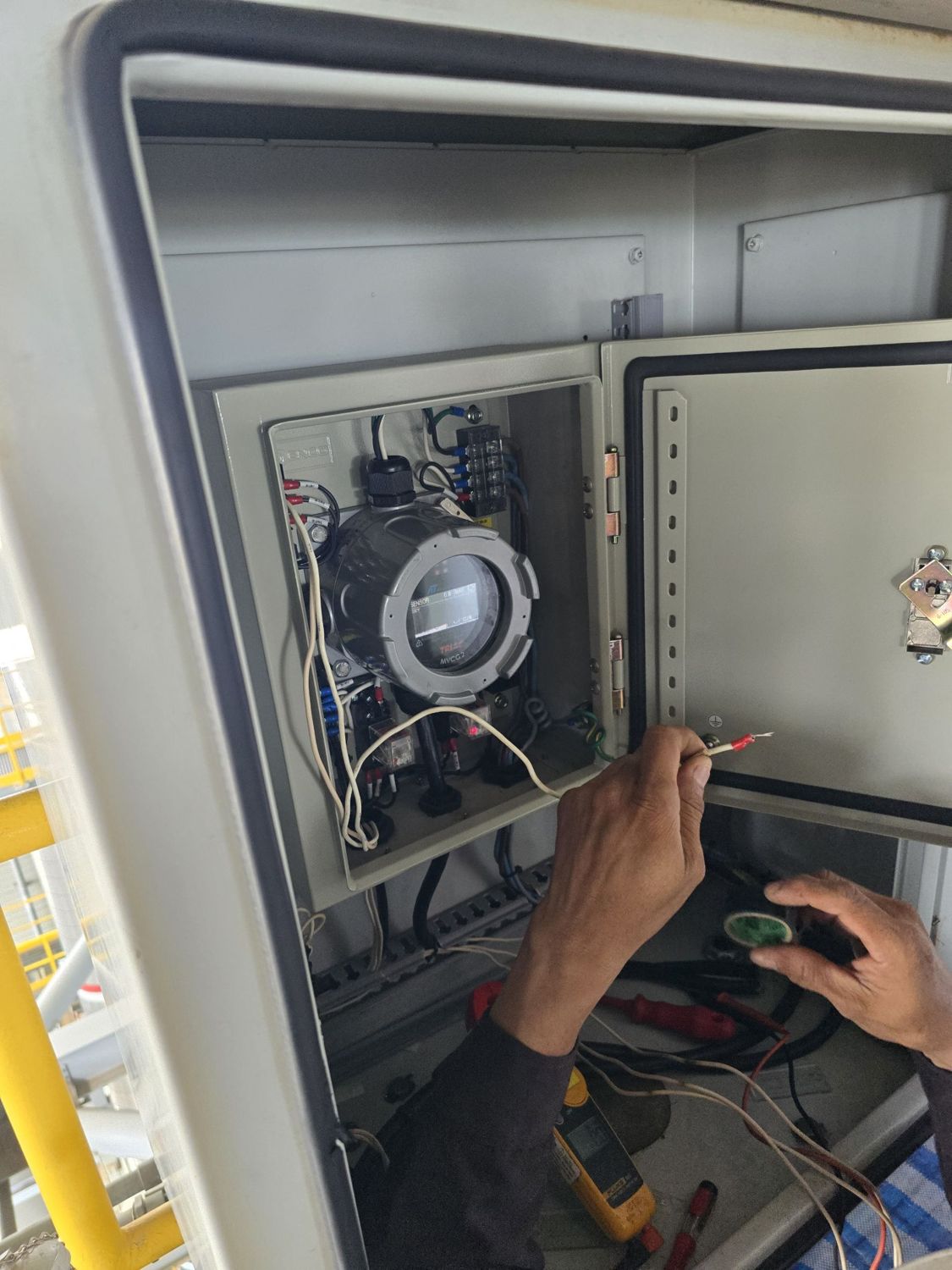
Actuator and positioner calibrated across the full signal range and verified at 0 / 25 / 50 / 75 / 100 %, then delivered with a test certificate and report.
Overhaul procedure
Our controlled procedure follows the valve from receipt to certificate, with photo and inspection records taken at every stage.
Photo, mark & record
Photograph from all sides, punch-mark matching components, and record the name-plate data (class, rating, bench set, signal range) onto the inspection sheet.
Disassemble
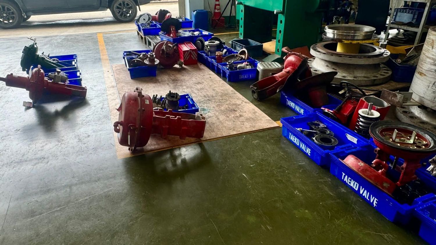
Release air and signal lines, separate the actuator, then dismantle bonnet, plug, stem, packing and seat ring — protecting sealing surfaces throughout.
Inspect & analyse
Check body and flange faces for cracks and wear, seat and plug for damage, stem for straightness, and diaphragm and spring for condition.
Clean & repair
Wire-brush threads and stems, machine and lap seat & plug, align or replace the stem, and renew diaphragm, packing, gaskets and O-rings.
Reassemble
Reseat the seat ring, refit plug, stem and packing, remount the actuator and reconnect air lines — verifying the plug does not touch the seat during set-up.
Body test & calibrate
Hydrostatic body test to ANSI B16.34 / API 598, then calibrate the positioner across the signal range and verify at 0 / 25 / 50 / 75 / 100 %.
Seat test, tag & report
Seat-leakage test to ANSI/FCI 70-2 for the required class, then paint, fit the name plate, and issue the test certificate and report.
Graded lapping to a fine finish
Seat and plug are lapped with grinding compound matched to their condition — typically Grit 280–320, stepping to 400–600 for a very-fine finish. Where damage is deep, the surfaces are machined first, then lapped until flat, glossy and uniform in color.
Stems are checked on the lathe with a dial indicator and aligned if bend exceeds 0.003". A stem is replaced if scoring in the packing area reaches 0.010", since deeper scratches prevent a reliable packing seal.
| Normal seat / plug | Grit 280 – 320 (fine) |
|---|---|
| Very-fine finish | Grit 400 – 600 |
| Stem straightness | aligned if bend > 0.003" |
| Stem replacement | packing-area scoring ≥ 0.010" |
Body repair welding is performed to qualified procedures per ASME Section IX (repairs to ASME PCC-2), with dimensions and ratings to ANSI B16.34; a body is rejected if wall thickness has dropped below standard.
Verified across the range
The positioner is set to the name-plate signal (e.g. 3–15 psi) and supply, zeroed and spanned so travel tracks the signal. Calibration is verified at five points across the stroke — 0 / 25 / 50 / 75 / 100 % (3 / 6 / 9 / 12 / 15 psi) — together with accessories such as air booster, quick-exhaust and air-set.
Seat-leakage classes
| Class II | 0.5% of rated valve capacity |
|---|---|
| Class III | 0.1% of rated valve capacity |
| Class IV | 0.01% of rated valve capacity |
| Class V | metered water leakage per orifice |
| Class VI | air / nitrogen, per leakage table |
Class I is tested by agreement between customer and vendor. The class is selected to suit the trim and application.
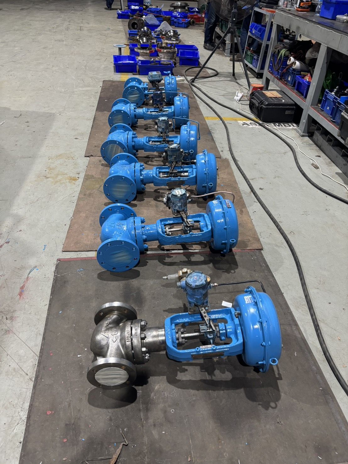
Control valve gallery